Die Cutting vs Digital Cutting: Tooling Cost, Speed, and Versioning
TLDR
In die cutting vs digital cutting, conventional die cutting is generally the stronger starting point for stable, repeat work produced at meaningful volume. Die-free digital cutting is often better suited to prototypes, short runs, multiple versions, and designs that may still change. Neither method is universally cheaper or faster: the right choice depends on tooling, setup, quantity, material, shape, finishing operations, and how many versions must be produced.
The practical mistake is treating die cutting vs digital cutting as a contest between old and new technology. It is really a production-planning decision. A physical die requires an upfront commitment but can support efficient repeated production. A digital cutting table reads cut data from a file and avoids a shape-specific cutting die, making revisions and changeovers easier. The best estimate follows the entire job from approved artwork through cutting, waste removal, packing, and shipment.
What is the difference between die cutting and digital cutting?
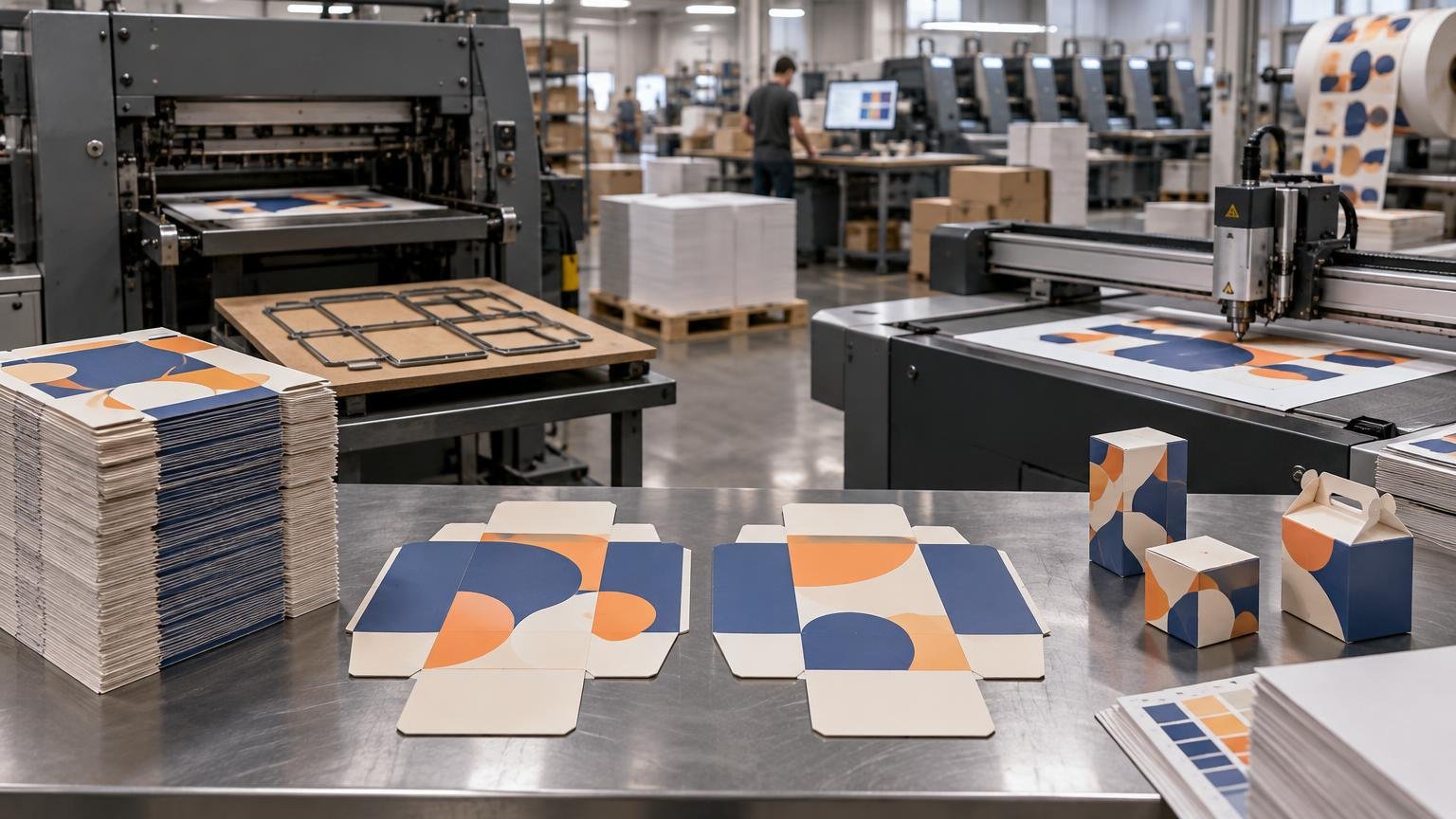
Conventional die cutting uses physical tooling to cut or form printed material. Depending on the equipment and application, the die may work in a platen, cylinder, rotary station, or dedicated punch system. Heidelberg, for example, describes a label workflow in which a precut stack is fed to a stamping punch and pressed through a cutting die. That is one clear example of a physical-die process rather than a universal description of every die cutter.
Digital cutting, as used in this guide, means die-free cutting performed by a software-controlled flatbed table or similar system. The machine follows vector paths and uses an appropriate tool for the material and operation. Summa documents flatbed workflows with interchangeable tool modules as well as camera-assisted contour cutting for printed flexible and rigid substrates.
The phrase “digital die cutting” is ambiguous. Some suppliers use it for die-free knife, routing, or creasing-table work. Others may use it more broadly for digitally controlled finishing equipment, including systems that still rely on physical tooling. Ask whether the quoted process needs a shape-specific die, which tools will be used, and whether creasing, perforating, or stripping is included.
Terms a print buyer should know
- Dieline: Vector artwork defining cut, crease, perforation, or other structural paths.
- Contour cut: A cut path that follows the perimeter of printed artwork rather than a simple rectangle.
- Kiss cut: A controlled cut through the face material while leaving the backing liner substantially intact, commonly used for sticker sheets.
- Through-cut: A cut through the full construction, producing separate pieces or removing a complete blank.
- Makeready: The setup and adjustment needed before saleable production begins.
- Stripping: Removal of surrounding waste after cutting.
- Blanking: Separation of finished blanks from the sheet after cutting and stripping.
- Registration: Alignment between the printed image and the cut or crease position.
Side-by-side production comparison
| Decision factor | Conventional die cutting | Die-free digital cutting |
|---|---|---|
| Cutting method | A physical die or cutting form applies the required geometry. | A software-controlled tool follows vector paths from a cut file. |
| Upfront preparation | Requires tooling manufacture plus press setup and makeready. | Requires file preparation, tool selection, registration setup, and machine setup, but no shape-specific cutting die. |
| Artwork revisions | A geometry change may require a modified or replacement die. | A geometry change can often be handled by revising the cut file, subject to material and tool limits. |
| Version changes | Best when many pieces share stable geometry. | Well suited to jobs with several shapes or frequently changing versions. |
| Production speed | Can deliver strong throughput on stable repeat work once set up. | Job speed depends heavily on path length, tool motion, material, sheet handling, and the number of operations. |
| Finishing range | Production systems may combine cutting, creasing, scoring, perforating, stripping, blanking, or embossing. | Tables may cut, crease, perforate, or route when fitted with suitable tools, but capabilities vary by machine and material. |
| Waste and handling | Efficient layouts and automated stripping can help at volume, although tooling and makeready create their own setup commitment. | Avoids discarded physical dies when shapes change, but intricate paths and manual part removal may add machine or labor time. |
| Best starting point | Stable designs, repeated orders, production quantities, and integrated converting. | Prototypes, samples, short runs, versioned work, and designs that are not yet stable. |
Conventional equipment should not be reduced to “a fast way to cut an outline.” Heidelberg’s Promatrix literature describes configurations supporting operations such as cutting, creasing, embossing, scoring, perforating, stripping, and blanking. That integration can matter more than raw cutting speed because the objective is a packed finished product, not merely a cut sheet.
Likewise, digital cutting is not just a plotter tracing an edge. The workflow may involve optical registration, multiple tool passes, crease rules, cut-depth control, and part removal. Esko documents a converting workflow that outputs a print PDF and a separate cutting file for a Kongsberg table, illustrating why printed graphics and structural data must remain coordinated even when no physical die is made.
How tooling cost, speed, and versioning affect the estimate
Tooling cost is only the first line item
A conventional estimate can include the physical die, setup, makeready sheets, press time, stripping, blanking, labor, packing, and freight. A digital estimate may avoid a physical cutting die but still includes file review, registration setup, cutting-table time, tool changes, material handling, waste removal, and packing.
That is why there is no responsible universal break-even quantity. A simple perimeter may cut quickly on a digital table, while an intricate sheet with many internal cuts can keep the tool moving for much longer. Conversely, a die may be expensive for a large or complicated structure, but its cost can be distributed across repeat orders if the design remains unchanged. For a fuller view of those cost components, see how commercial print estimates account for setup, waste, finishing, and freight.
Speed means total elapsed production time
Published machine speed is not the same as finished-job throughput. Heidelberg has published ratings around 7,500 to 8,000 sheets per hour for particular conventional die-cutter models, but those specifications should not be treated as a promise for every stock, format, finishing sequence, or plant. Saleable output can be constrained by feeding, registration, stripping, blanking, inspection, packing, or another upstream or downstream operation.
Digital cutting avoids the wait to manufacture a die and can move quickly from an approved file to setup. During production, however, the tool must travel around the specified paths. More shapes, smaller radii, internal openings, multiple tool operations, and difficult handling can increase cycle time. A comparison should therefore use estimated finished pieces per hour and total schedule—not a machine’s headline speed alone.
Versioning can change the decision
Suppose a campaign needs ten carton graphics but all ten use the same structural shape. The printer may be able to reuse one conventional die, so the number of printed versions does not automatically require ten tools. If every version has different windows, outlines, or dimensions, the tooling commitment changes substantially.
Digital cutting is especially useful when structural versions change because a new vector path may replace a new physical die. That does not make every version free: each file still needs preflight, nesting, setup, identification, inspection, and correct packing. Version count should appear as a separate specification on the quote rather than being hidden inside the total quantity.
The production challenge is not new. A PRINTING United Alliance report on digital folding-carton production discusses finishing and die cutting as a difficult part of short-run packaging workflows. It provides useful process context, although it should not be read as a current performance guarantee for any particular machine.
Which process fits common print jobs?
Fifty prototype folding cartons
Start by pricing digital cutting. Avoiding a production die can reduce the commitment while dimensions, locking tabs, panels, and graphics are being evaluated. The sample still needs the intended board—or a properly disclosed substitute—and realistic crease settings. A prototype made on different material may assemble differently from the production carton.
Twenty-five thousand identical cartons
Start by evaluating conventional die cutting, especially when the structure is approved and likely to repeat. Physical tooling and makeready may be spread over more units, while integrated creasing, stripping, and blanking can support production flow. The final choice still depends on sheet format, board, imposed yield, die complexity, available equipment, deadline, and the cost of handling finished blanks.
Two hundred sticker sheets with 20 shapes
Digital contour cutting is a logical first quote because it supports many cut paths without commissioning a shape-specific die. Confirm whether the job needs kiss cuts, through-cuts, or both; whether the liner must remain intact; and how close the cuts sit to printed borders. Buyers comparing custom sticker production should submit the finished size, sheet size, face stock, adhesive or liner requirements, lamination, quantities, and contour file rather than asking for a price based only on “200 sticker sheets.”
Sticker construction affects cutting behavior. A face material, adhesive, release liner, ink, and laminate form a system, so a successful cut is not defined by shape alone. For adjacent buying considerations, see the guide to name tags and sticker formats for events, schools, and businesses.
A rigid-board retail display
Begin with a digital table assessment, particularly for a prototype or limited rollout. Flatbed systems can be configured for printed rigid substrates and registration-based contour work, but the appropriate tool and practical capacity depend on the machine, board construction, thickness, cut quality, and required edge finish. A long repeat run may justify purpose-built tooling or another converting method, so the prototype method should not be assumed to be the production method.
Shaped cards, invitations, and hang tags
Quantity and design stability should drive the first estimate. Digital cutting can suit a short run with several silhouettes or personalized shapes. A stable design ordered repeatedly may justify a die. Also specify whether the product needs scoring, perforation, holes, rounded corners, foil, lamination, or other finishing because those operations may determine the route more than the outside shape does.
Artwork and production checklist
A useful quote starts with a production specification, not a thumbnail of the design. Prepare the artwork according to the provider’s requirements and keep structural paths separate from printable graphics. The broader print-ready file setup guide explains related bleed, image, color, and file-preparation issues.
- Finished dimensions and flat sheet size, with the unit of measure clearly stated.
- A vector dieline or contour path showing cut, crease, score, perforation, and fold instructions on separate named layers or spot colors as requested.
- Bleed beyond every printed edge that will be cut, plus a safe area for text and critical graphics.
- The required print-to-cut alignment, especially where a narrow printed border makes small movement visible.
- Exact substrate, caliper or thickness, grain direction where relevant, and any corrugated flute or board construction.
- For pressure-sensitive work, the face stock, adhesive, liner, and whether each path is a kiss cut or through-cut.
- Coating, varnish, lamination, foil, or other finishing that may change tool selection or production order.
- Total quantity and a version schedule showing the quantity of each graphic and each structural shape.
- Packing requirements, including flat versus assembled cartons, bundle counts, labeling, and version separation.
- Proofing needs, delivery destination, required arrival date, and whether the schedule has time for structural testing.
Do not assume the same file can move unchanged between a digital sample and conventional production. The underlying structure may be reusable, but the production provider may require different line conventions, allowances, crease compensation, nesting, or manufacturing marks. Preserve an editable structural master and let the finishing provider adapt a controlled production copy.
Frequently asked questions
Does digital cutting require a physical die?
Die-free digital-table cutting does not require a shape-specific physical cutting die. It does require a valid vector cut file, suitable tools, machine setup, and registration when cuts must align with printing. Because “digital die cutting” is used inconsistently, verify the supplier’s exact process.
Is digital cutting always cheaper for short runs?
No. It often avoids tooling expense, but complex paths, slow materials, several tool operations, and manual part removal can make table time and labor significant. Compare complete delivered estimates using the same material, quantity, finishing, packing, and schedule.
Can both methods crease and perforate?
They can when the selected equipment and tooling support those operations. Conventional production systems may combine cutting with creasing, scoring, perforating, stripping, and blanking. Digital tables may offer multiple tool modules, but capability is machine- and material-specific. Ask for a structural sample when fold quality or perforation behavior is critical.
How does print-to-cut registration work?
A registration system identifies marks or printed features and uses them to align or adjust the cut path to the printed sheet. This can compensate for some placement, scale, or distortion effects within the system’s workflow, but it does not eliminate the need for bleed, safe areas, stable media, accurate files, and realistic tolerances. Summa’s documentation describes optical workflows for contour cutting printed materials.
Choose the process from the finished product backward
Use conventional die cutting as the first candidate when the structure is stable, the quantity or repeat demand can justify tooling, and integrated converting operations improve production flow. Use die-free digital cutting as the first candidate for prototypes, short runs, multiple structural versions, and work likely to change.
Then test that starting point against the actual job. Provide quantity, version count, material construction, finished dimensions, cut complexity, crease or perforation requirements, packing method, and deadline. Ask the printer to compare total delivered cost and schedule, including tooling, makeready, waste, finishing labor, and repeat-order implications. That produces a more reliable decision than choosing between the two processes by unit price or machine speed alone.